
Day two of the build I spent more time, still had a lot of fun but also experienced the first issues, that still haven’t been resolved…. I also did a first test render of a time-lapse movie of the whole build, lots of fun! May or may not be published and posted here. ![]()
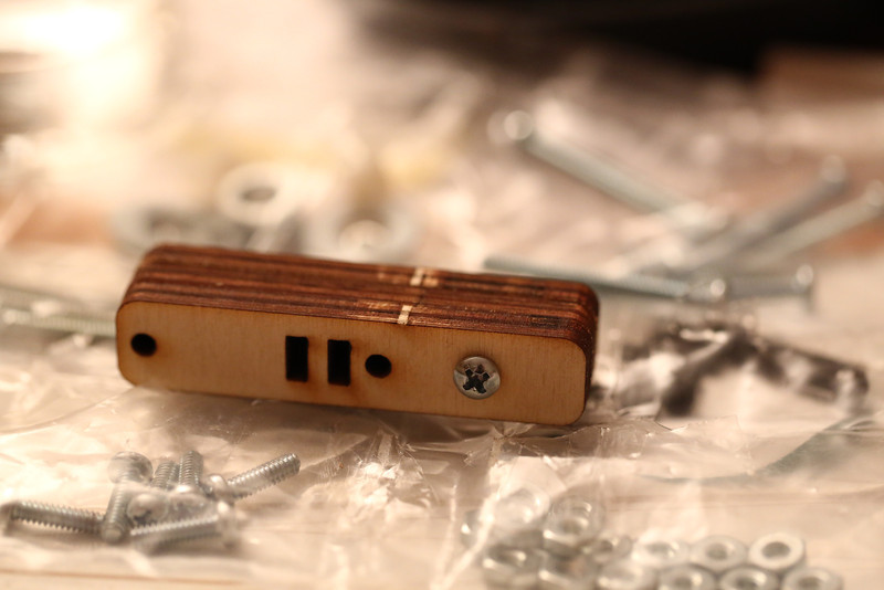
Early on day two I realized what I first looked like a tiny little wrench (but ignored for a while since I also thought it might be a weird new component for the printer) actually was a little wrench! Cute and quite helpful.
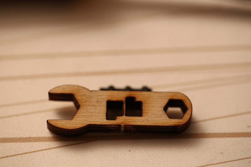
Tiny printrbot LC wrench!
Started before the kid went to sleep so I could pound the Z rods in. They were a bit tricky. I started out by sanding the holes at the top to even get them through, but on the bottom holes I used a rubber mallet with support under the bottom. Worked fine, but made a lot of noise.
Had to do a lot of sanding of the holes for the X/bed hinge rod as well. They were extremely tight. Would have been much easier to do before the base was mounted but taking it apart again after forcing the Z rods in was not an option. I took the screws off the X stepper to move it a few millimeters away so it would be a little bit easier to avoid damaging it. As a general rule from this point on I made sure to sand all of the holes for rods before assembling them.
Z rods and X/bed hinge finally in place!
X rods installed.
It was a little tricky to tighten the X belt, felt like I got it pretty tight but after having carefully zip tied it I’m not sure if it’s good enough.
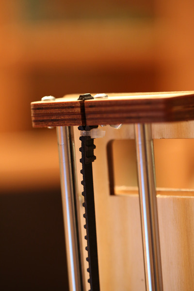
One of the zip ties on the X axis belt.
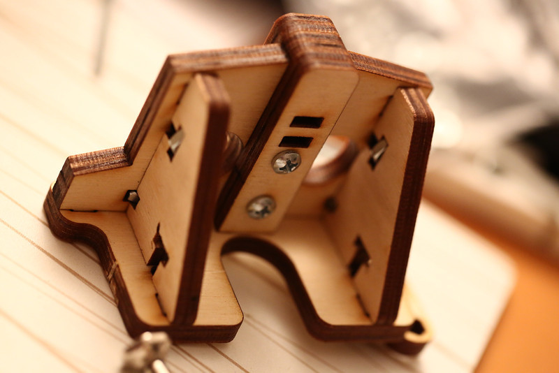
Next up was the Z coupler for the Z screw. I had already noted that the groove in one of the parts looked a bit weird, but didn’t realize how bad it would be. I first had an insane amount of wobble, it was really crooked. For now I’ve used some pieces of zip tie plastics to shim it but there’s still plenty of Z wobble. Have been googling and found some interesting options on ebay (aluminium couplers) but there’s also printable options. Let’s just hope I can get the wobble down to the bare minimum needed to get prints done.
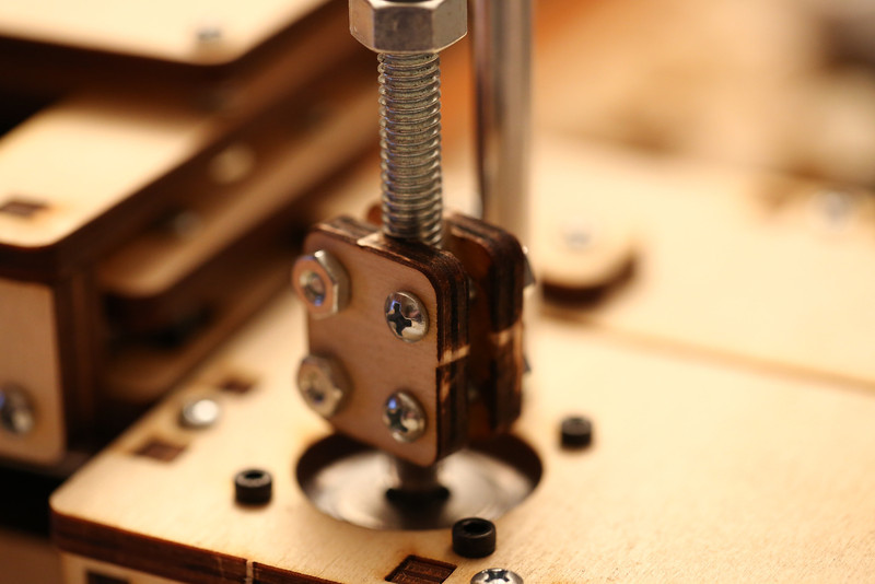
The bad Z coupler.
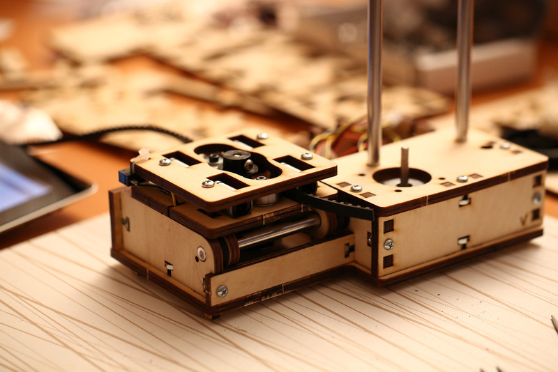
The Y/Z sandwich was next. Lots of fun, had to sand a little bit to get the linear bearings to fit in the middle piece. Otherwise pretty easy to assemble actually.
The nut trap for the Z axis is mounted using very long screws, lots of fun if you’re using a regular screwdriver!
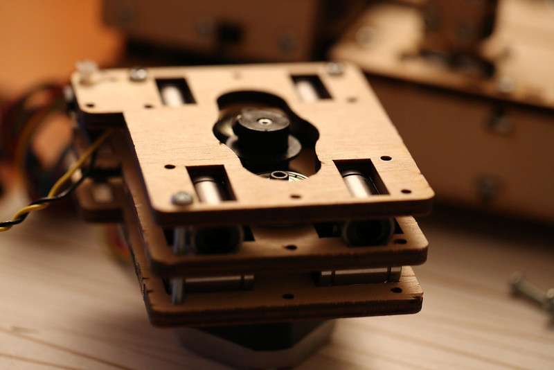
Y/Z sandwich done!
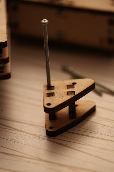
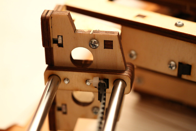
Time to get the ends of the Y axis together, nice feeling to see the pile of LC parts quickly shrinking to nothing. Less fun was the missing screws. I’m out of longer screws now, only a 1.75 inch left and that’s way too long. Needed one more 0.75 and one of the elusive 1 inch screws. So the back end of the Z axis is currently held together with one single screw. It feels surprisingly solid though. But I’m going to get an ISO M screw with some nuts to least have one that I can adjust the end stop with. It’s next to impossible to buy non-metric screws here, I’ve tried before to get screws for a server rack mount and they guy we sent to the local shops was laughed at for even asking…
The Y end that’s missing two screws…
The front Y end, aka the extruder mount.
Tightening the Y belt felt a bit easier than the X belt, perhaps because I had a tiny bit of experience. ![]() I hope it’s tight enough, if it isn’t I’ll look at printed belt tightening options sooner rather than later!
I hope it’s tight enough, if it isn’t I’ll look at printed belt tightening options sooner rather than later!
One of the zip ties holding the Y belt.

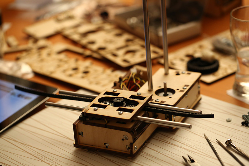
Y assembly done! Belt pretty tight, will be interesting to see if it’s tight enough.
It was pretty to easy to get the big sandwich onto the Z rods, also adjusted the Z endstop, will add another nut for it to get less wobble. Saw that Brook had two in his video, only one in the instructions though. This looks nice as well.
Very happy with the progress during day 2!
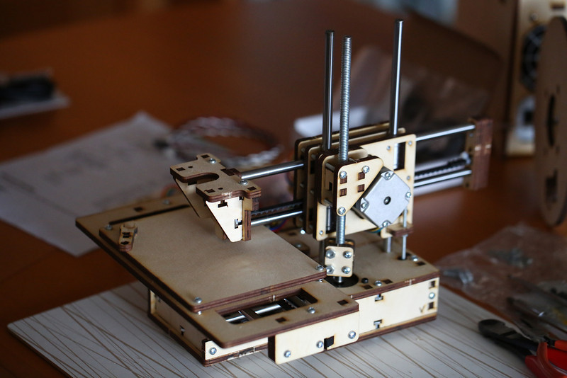
Progress after day 2.
So what’s left to do now is assembling the extruder/hot end, mounting it on the printer, make the cabling a bit more sane and finally get the printrboard in there. The latter looks a bit tricky actually, there’s a lot of cables and very little room. Would have been nice with some spare connectors and simply cut the cables where appropriate to get custom lengths instead.
Nice summary. We are just behind you on the build process – it is fun to read about your experience before we launch into the next section. Our box did not come with a BOM, but saw yours and reposted the pic which shows the motor sticker. Their website still shows 3 small and 1 large motor. Thanks again for the details!
Happy that my posts are helping people! Haven’t seen many build logs before so I’m doing my best to at least share some of it. It’s a bit strange that they haven’t updated the BOM but I guess it’s tricky since there are multiple revisions out there. So getting a printed copy like I did is quite helpful.
Fun to follow your build as well, saw that you were missing screws that I had and instead had the ones I needed (more) of.
Pingback: Printrbot jr assembly part 1 | Christian Kullander
Just pulled the trigger on mine so I’ll be back before long