First successful prints on the Printrbot Jr

[Please read the Printrbot Jr assembly posts first for some context]

After switching to Slic3r and doing some very basic configuration it failed at slicing the Mini Mr Jaws that went really wrong before. So instead I took the very similar Mini Mr Alligator and it sliced perfectly fine. It was with both excitement and some trepidation I pressed print… But it turned out to a close a complete success, the only bad thing was that I hadn’t saved the bed dimensions correctly in the Slic3r settings so the print got placed in the uppermost quadrant of the bed. Amazed at how well it turned out given the very minimal calibration!

The next print i tried was simply doubling the size, it also turned out well after issues with the first layer not sticking. Had to switch out the tape, then it worked fine.
The Alligators!

The Alligators!

After these two successes I wanted to try something very different, and that also showed that a printer like this can’t just print smalll solid toys and similar. So I went to Thingiverse and grabbed a vase I’d liked earlier, one of the variants of the Kochflake vases. Tried different slicing settings to get rid of the top filled layer and chose a perimeter (wall thickness) of 2. This print took quite some time, almost 2 hours, and especially the height was very close to the maximum height available. The Z rods were at the end inside the top two linear bearings.

The print looks very nice. Had two issues, one was the first layer where the second half of the infill didn’t stick correctly and bunched up a bit. On the second layer that meant that the extruder nozzle bumped into them but it still went pretty good. The other problem is that you really can’t use the same (high) speed for the top layers. The instability of Jr when Z gets high means there’s plenty of layer misalignment problems for top centimeters.

I also have a very anoying and loud vibration issues with the X axis unfortunately, not sure what to do about it.

The Kochflake vase

The Kochflake vase

Closer look at the vase

Closer look at the vase

Printrbot Jr assembly part 4

After spending lots of time with other things, such as re-purposing an old Eee PC for use with the printrbot, I finally sat down with the build again.

Left to do was testing the Eee, getting the printrboard mounted and the cabling worked out as well as some initial calibration work. First of all I had another look at the Y axis, the belt really did need tightening. Just tightening it by hand again and adding a new zip tie felt like a bad idea since getting the zip tie off to tighten it every time isn’t fun, I really don’t want to damage the belt. Without anything printed to use and nothing else that could be reused in a sane way I once more turned to using filament pieces and it worked out quite well actually!

Quick and dirty filament tensioner.

Quick and dirty filament belt tensioner.

Closeup of the sharpened filament ends

Closeup of the sharpened filament ends

I’m a bit worried though since I seem to have an issue with the top Y rod being slightly longer than the other. The loose fit of the top rod in the front extrusion mount and the belt mostly pulling on the bottom part the makes the extruder tilt slightly forwards. The loose fit is my fault, it was extremely tight at first so I couldn’t get the rod in, I then sanded too much probably. Solutions such as trying to grind one rod slightly, switching rods with the the longer one at the bottom instead and possibly using epoxy to make sure they aren’t so loose are solutions I’ve contemplated. But I’m leaving it for now to see how bad it is when printing.

Then I finished the zip tying of the cables, hooked them up again to verify everything worked with the Eee (and it did, running Fedora Core 18 with pronterface) and then started to try getting the board into the base. Had to re-route some cables and redo some zip ties but finally I got it in place. And it still worked, was a bit worried. :-) Heat dissipation really won’t be good in that small unventilated space but given how small it is it’s not easy to do something about. Also not sure how hot it gets during printing.

Printrboard going in.

Printrboard going in.

Printrbot fully assembled!

Printrbot fully assembled!

Continued with lubricating the Z rod, used a liquid lubricant with PTFE, which seems to a favored method. Have some weird resonance noise during Z movement now, helps if I tap the rod. Perhaps it has slid down and is barely touching the motor shaft? Not a big problem. The wobble is under control at least.

Then I mostly followed the getting started guide and did max X and Y measurements, result was 136×120 mm but I could probably squeeze in another millimeter or two with some adjustments. Or mod the bed to stick out longer in the front, there’s lots of unused Y reach that’s not being used now. I covered the bed in masking tape, haven’t found a local source of 3M blue tape yet, the best wide masking tape I could find was yellow Tesa tape which claims it can stay on for 8 days without leaving residue. With the tape on I could perform the bed leveling, using a piece of paper. It’s not perfect, but hopefully good enough?

Continued on with feeding filament into the extruder, had to adjust the idler pressure, it was too high it seemed like, very hard to get the filament in. Then I heated up the hot end in Pronterface and extruded some plastic. Took quite a few careful extrusions of 5 mm at a time before I got a result, was a bit nervous for a while after hearing horror stories before of melted plastic filling up the extruder and making mess. But it went fine, clear strings of PLA were squeezed out of the nozzle! Time to calibrate E, which was pretty easy.

Extruded PLA when calibrating the E value.

Extruded PLA when loading the filament and calibrating the E value.

Since skeinforge is nicely packaged in Fedora Core 18 I thought it would be nice to have a go at using it instead Slic3r. So I did a rough configuration of skeinforge, had to google a lot. I know now a lot of gcode compared to before… When I thought it was fairly OK I went ahead to try to print my test subject, the Mini Mr Jaws. It did not work out very well… I thought things looked quite weird when the skirt was printed and then the craziness just continued, way too much PLA was being extruded so I aborted the print. It does look fairly promising though, if I can get the extrusion right. It seems to stick very well onto the tape.

Fail aka my first blob.

Fail aka my first blob.

By that time it was after midnight so I gave up for the day since the print takes a pretty long time (pronterface guessed 51 minutes). The next day I went to get some tools that can be useful. The IR thermometer was a lot of fun, I’ve already used it a bit in the kitchen, on members of the family, bath water etc.

Bought some more tools; micrometer, feeler gauges, spatulas, wide razor blade, IR thermometer, hobby knife set and moisture absorbers.

Bought some more tools; micrometer, feeler gauges, spatulas, wide razor blade, IR thermometer, hobby knife set and moisture absorbers.

I had another go at the skeinforge settings but have given up for now and instead packaging up the latest version of Slic3r on my main Linux box to use it instead. Hope to have a new post up with a successful print soon!

Links to the other parts of the build: part 1, part 2 and part 3

Printrbot jr assembly part 3

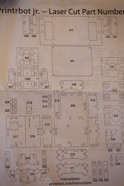
Time to have a go at the extruder, a little tricky since there is a good set of instructions for the wooden part of the LC extruder, but neither that or the Jr guide has any instructions for the gears, motor, hobbed bolt, the hot end itself etc. Luckily there’s nice instructions in the Printrbot Plus guide and also some in the Jr youtube video (part 5).
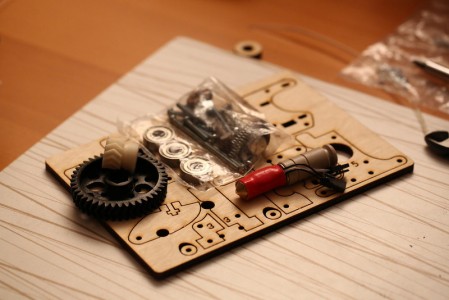
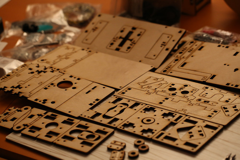
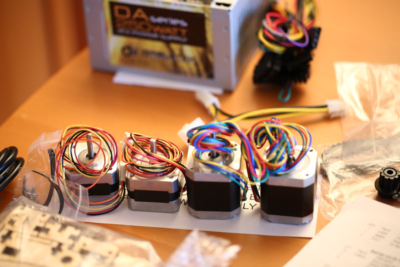
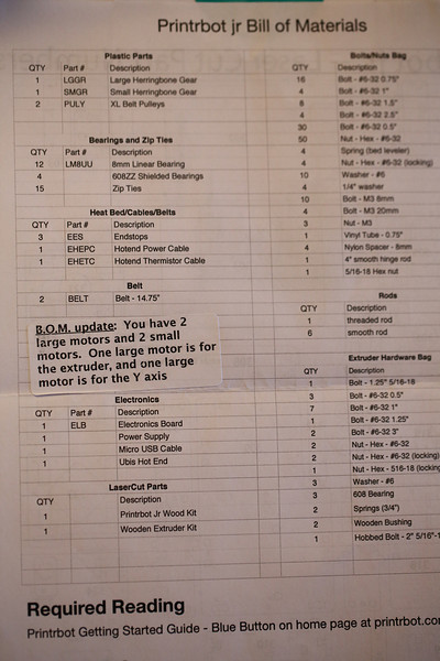
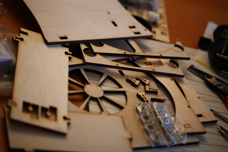
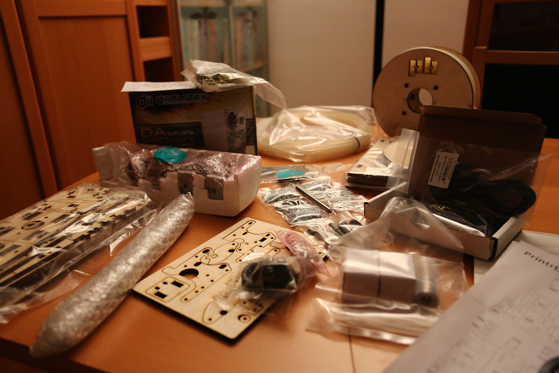
printrbot_extruder_parts

Extruder parts

printrbot_extruder_parts_laid_out

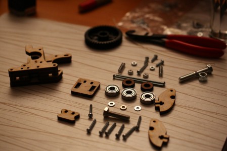
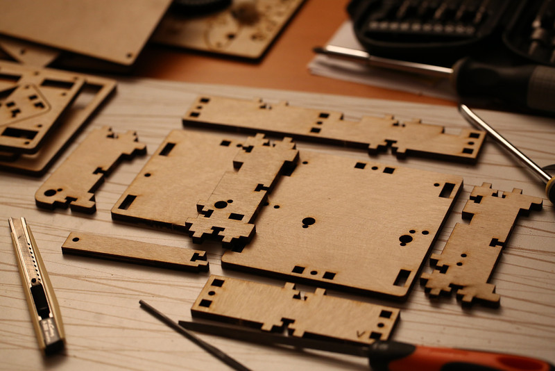
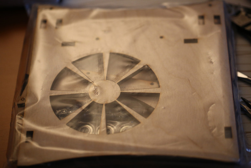
Extruder pieces laid out as in the step-by-step guide. Note the discrepancies…

Compare the picture above with the one in the guide and you’ll see that I have missing screws (again), perhaps they were intended to be included in the printer kit, I guess there might be different revisions with/without screws for both the extruder and the different printer kits. More on this later.

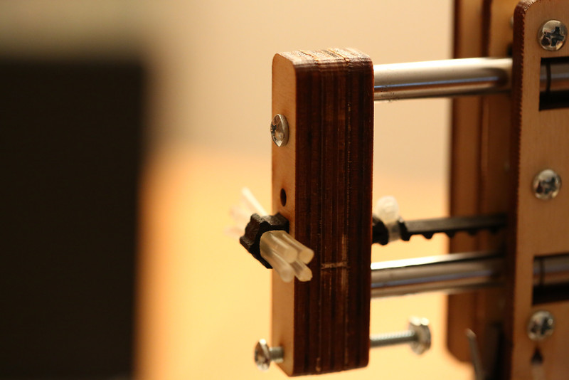
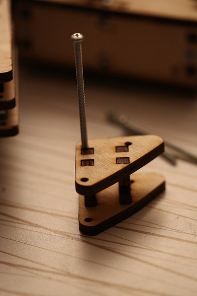
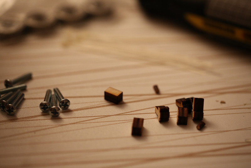
It wasn’t that difficult to keep the stack of pieces aligned before trying to put the screws in, then it got much trickier. I realized that instead of hex keys, toothpicks or other weird things I had the perfect material available! I simply snipped of few pieces of my 3mm filament! You need a pair of pliers to hold the small round washers of plywood at the ends still though, otherwise they’ll just rotate with the screws.

printrbot_extruder_stack_filament

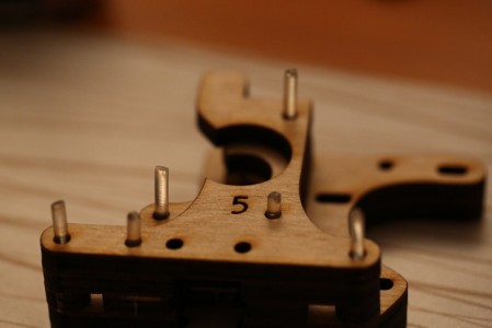
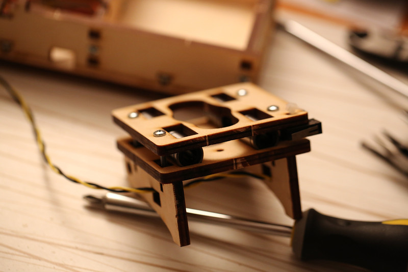
Extruder stack with filament pieces to help with alignment.
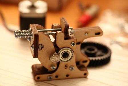
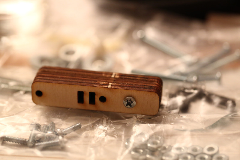
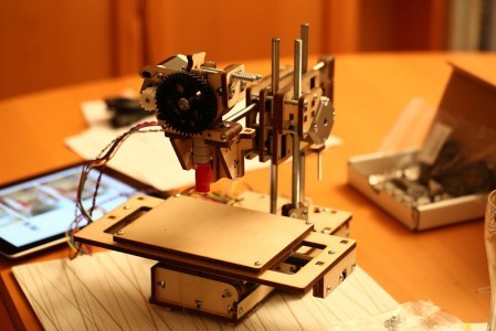
printrbot_extruder_done

Assembled extruder.

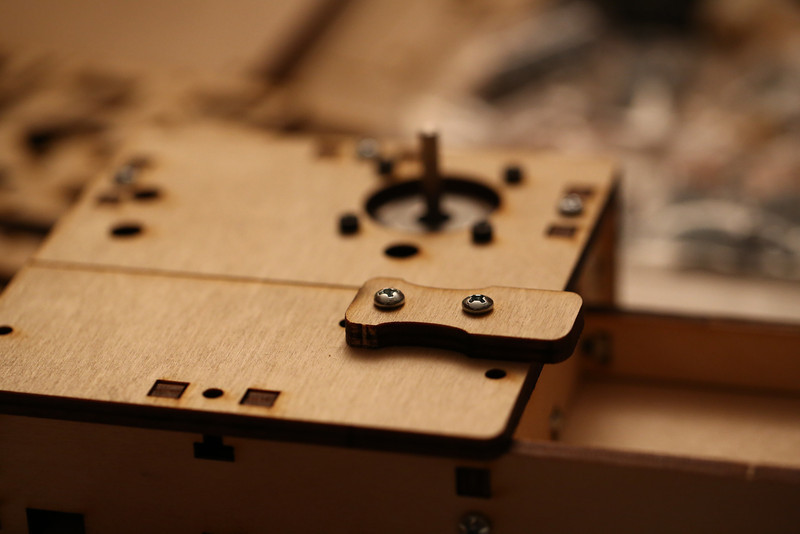
After the assembly I realized that two screws I had left was either enough to secure the hot end on the extruder, or to mount the extruder to the printer. I used those two 1 inch 6-32 screws to mount the hot end. Luckily I had investigated metric equivalents to 6-32 and found that M3.5 was close. Unfortunately no store that’s close had smaller than M4 but I did buy some 25 mm M4s with both regular and nylock nuts the day before. These proved to work pretty well to mount the extruder! The head of the screws are bigger so no washers were necessary, the only problem was the nuts that were smaller so I had to use pliers to hold them in. They probably weren’t necessary though, the M4 did self-tap the hole and held on nicely even without the nuts.

printrbot_extruder_mount_m4

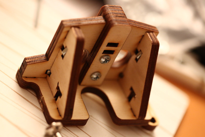
Testing using M4 screws to mount extruder.

printrbot_extruder_with_hotend

Added the hot end, about to mount the extruder.

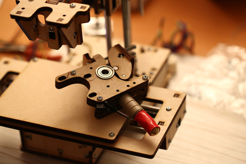
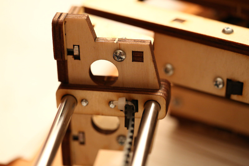
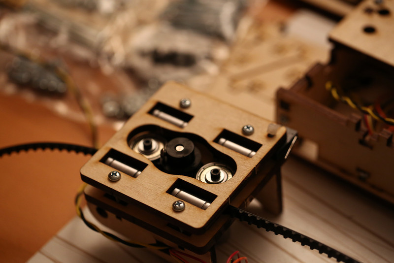
After putting in the screws that keeps the hot end in I moved on the hobbed bolt with the big gear. Geting the bolt all the way through into the big gear took a significant amount of force but it seems good now. I put it in to verify that I had a reasonable amount of pressure against it and it might even be too much, will have to see how it works in practice. When I tested on a piece of filament, turning the big gear by hand, it was pulled through very nicely and had small indentations on it after it’s encounter with the hobbed bolt! I fastened the hobbed bolt with a nylock nut, I had both available since one of them came in the printer kit bag of screws and nuts, but the regular nut did not work very well even when just turning the gear by hand. It also seems like it might be a good idea to put a washer between the gear and the bearing, seems to be a bit of friction there right now.

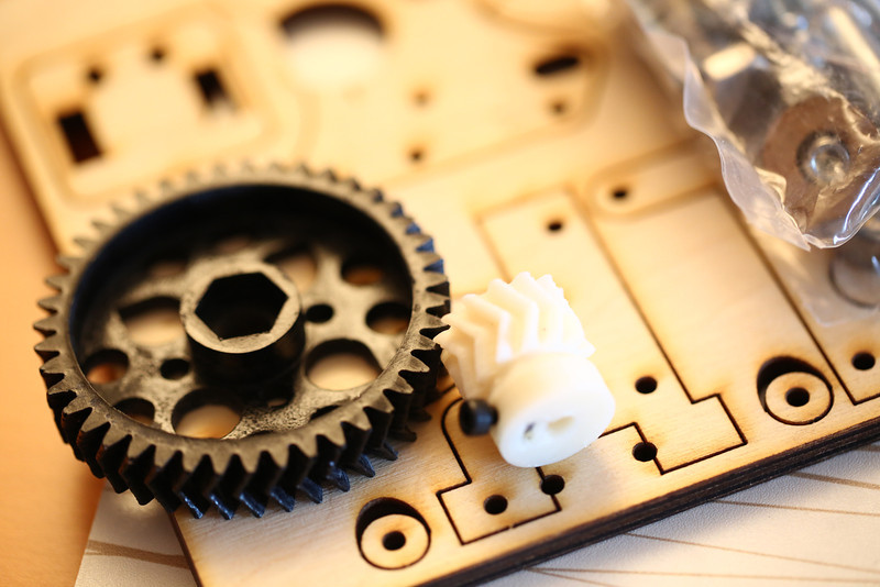
My small white pulley gear was way too tight, almost impossible to get on the motor shaft so I used a small needle file to make the center hole slightly bigger. Which allows it to (as recommended) self-adjust when turned with the big gear. My gears look very rough, but they seem pretty OK. When turning them by hand it feels like there is an occasional stutter though but I’m hesitant to try to randomly file away bits and see if it helps, I’d rather try to print new ones if they are a problem (unless it proves to be really bad of course).

printrbot_extruder_mounted

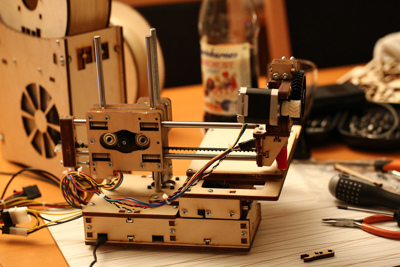
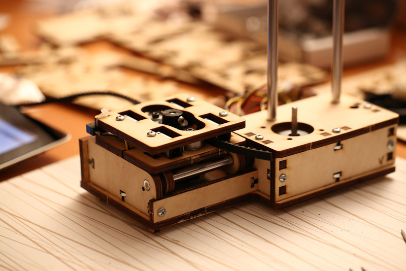
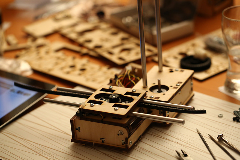
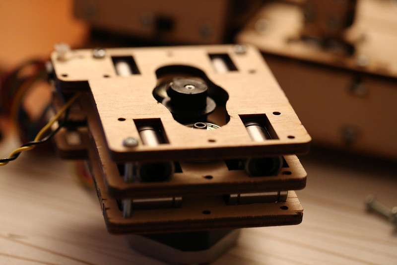
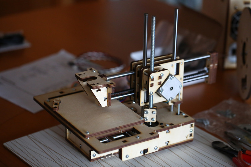
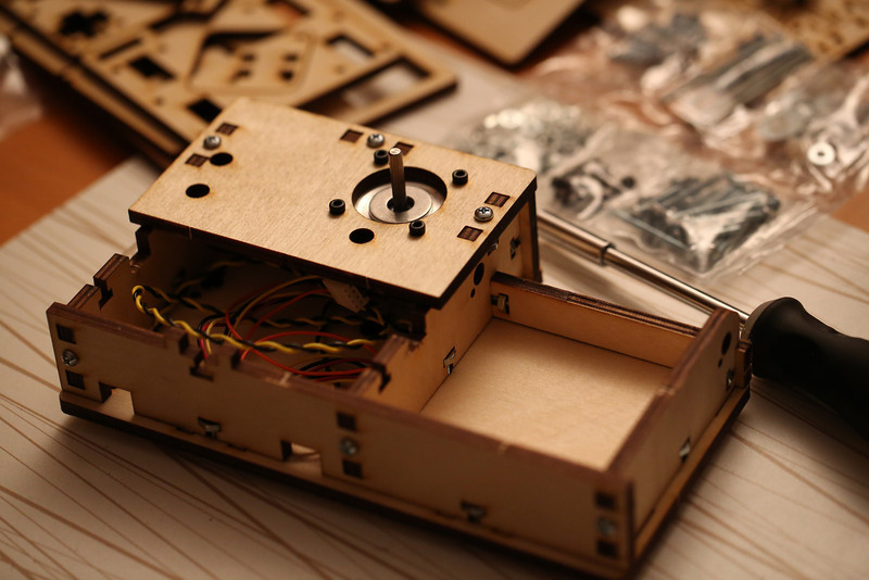
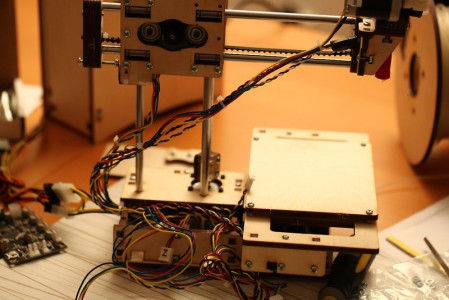
Extruder mounted, added stepper motor and the other bits and pieces.

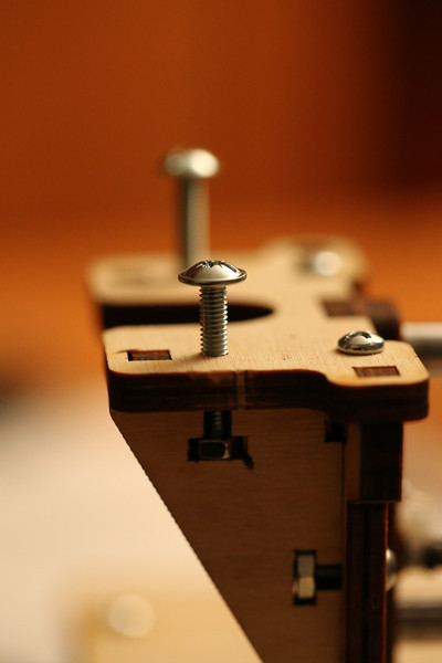
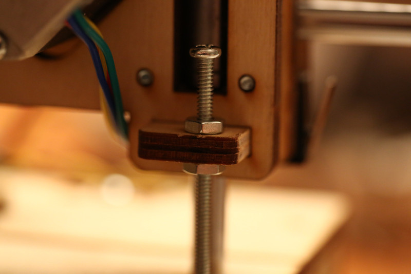
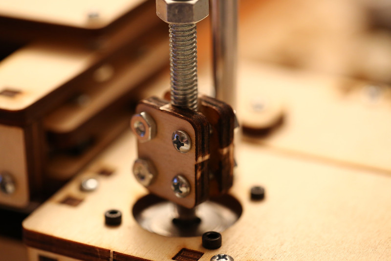
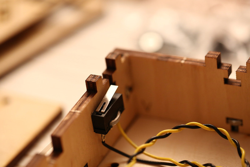
Then I went back to some things I postponed earlier. The Z coupler was the first. When turning the rod by hand now that the Y/Z sandwich is mounted and the nut captured the wobble no longer seemed that bad. I want to see how it works like this first before I take any further action. Next up was the Z endstop, I pulled it out, added a top nut and then did a much better rough adjustment, too at least prevent the hot end from smashing into the bed.

printrbot_z_endstop_screw_fixed

The Z endstop after adding a nut and adjustment.

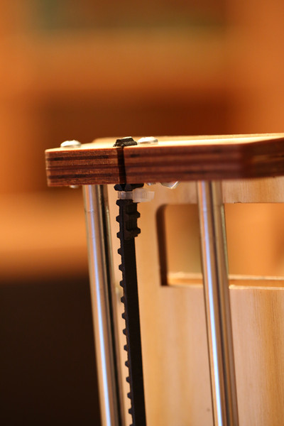
I also took the single very long remaining 6-32 screw and a nylock nut and added them on the rear end of the Y assembly since I realized that without it being there and adjustable the extruder went well beyond the end of the bed before hitting the end stop switch. While fiddling with the end stops I had a look at the X one. Which of course had issues as well… I moved the longer 6-32 screw and its nylock nut on one of the ends of the X rods back to where I had it been originally so it hit the end stop. Not sure why I moved it before, I believe one of the pictures in the guide confused me and caused me to move it, I do remember being confused later on about having a nut sticking out where there was no reason for it and to check on it later. That’s probably why I left the screw hole by the end stop empty, then I obviously forgot about it. Tip: Have a notepad next to you while building to make note of things like this instead of relying on remembering it.

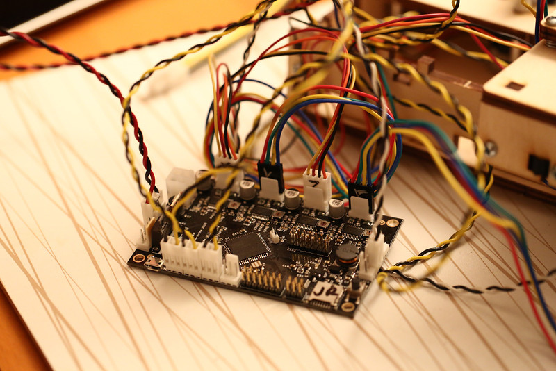
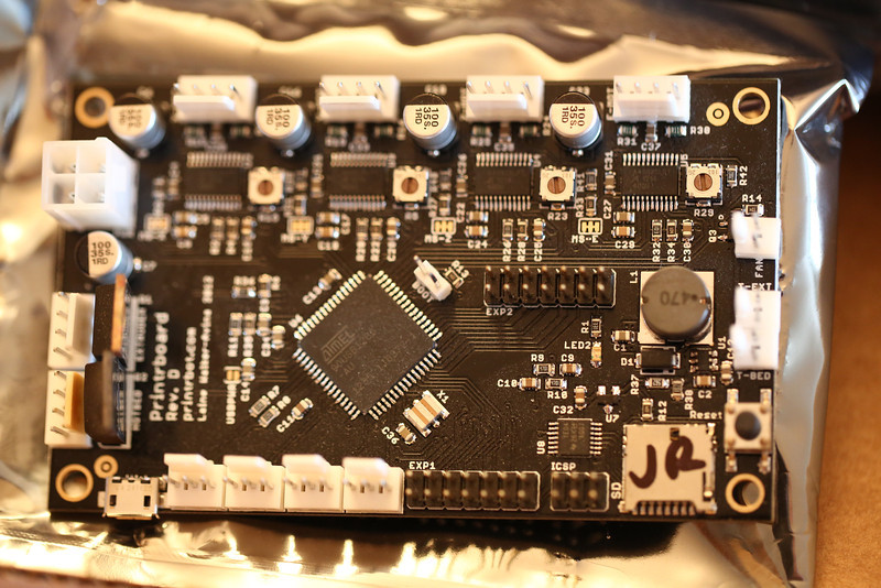
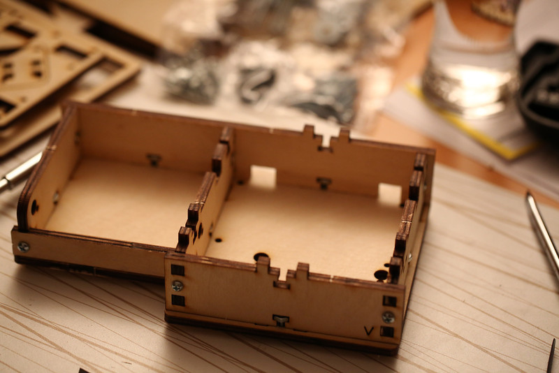
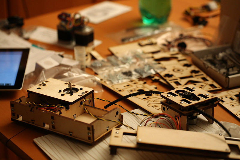
Finally it was time to do the first tests! I pulled off the lid of the base and pulled out the Z and X cables, hooked them and the rest of the cables up to the printrboard and powered it on. A green LED turned on which felt very promising. Connected the USB cable to my Macbook, launched Pronterface that I installed a few days ago and after selecting the right serial port it connected!

printrbot_everything_connected

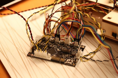
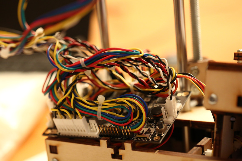
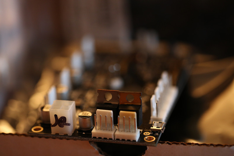
printrboard connected temporarily for testing, lots of cables.

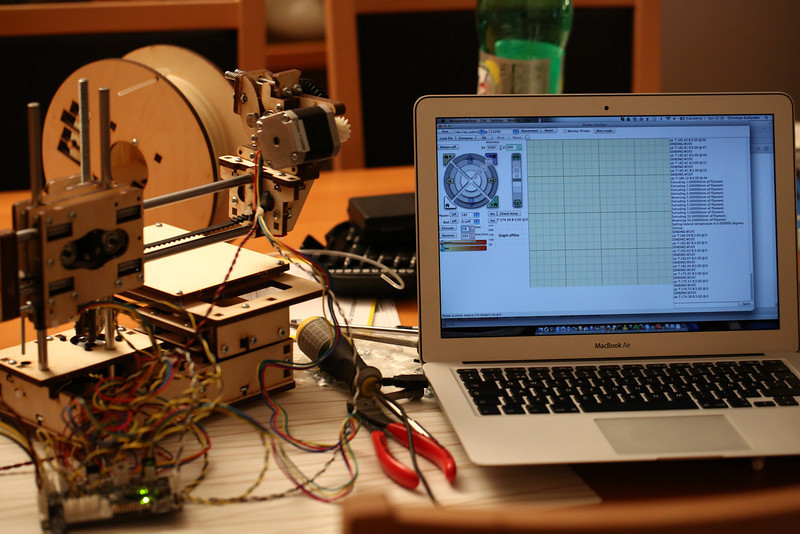
Fun to play around with stepping back and forth on X, Y and Z to begin with. Once more the Z rod doesn’t seem that bad. Took forever for it go home but the end stop adjustment was pretty good, will fine-tune it when I’ve added tape to the bed and leveled it. The X one was also good but when I tried the Y home button things went bad. It moved in the wrong direction (which I hadn’t realized before) and pulled pretty hard on the belt when it got stuck. Not sure why; if it slipped, got stretched or any other reason but it’s definitely less tight now. Won’t tuch it until after an attempt to print though. I had seen people asking about motors going in the wrong direction on printrbottalk.com before so I simply did what I remembered others telling them and simply reversed the connector. Then it worked fine!

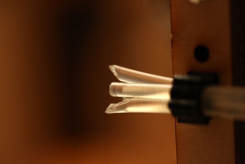
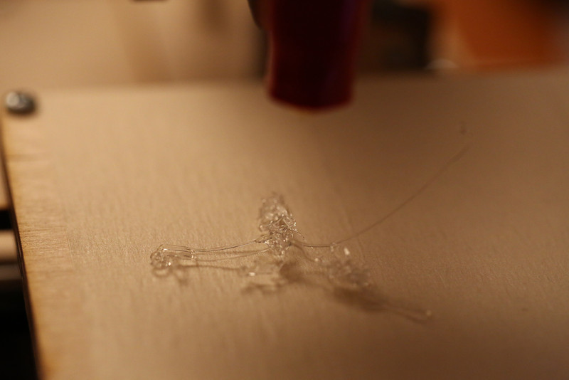
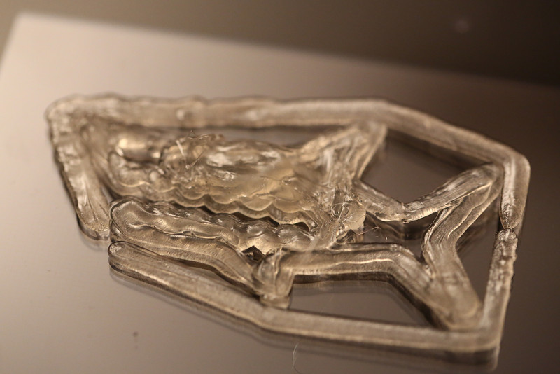
You can’t test the extruder with the hot end being cold so I chose to heat it up to 185 degrees. The hot end and termistor worked fine, and after it being heated up I extruded and reversed a few cm of filament (without any in the printer). Success overall! I did realize though that the extruder motor might have to be reversed also, it’s the same type of motor but I didn’t actually verify that the gears rotated in the right direction when “extruding” before.

printrbot_testing_w_pronterface

Testing with pronterface.

Pulled the cables out again and labeled all of the connectors, used a DVD marker for the white connectors and a silver colored pen for the black ones. Simply wrote X, Y, Z and E on the motor connectors, X S, Y S and Z S on the X/Y/Z endstops. And T E on the termistor for the extruder, Ext on the extruder heating wire

To get an idea on how much slack was needed on the cables I moved the extruder to the extreme Y and Z endpoints to check. Lots of zip ties later I had run out, will have to try to find my bag of small white ones to continue. So all that’s left before the first test print now is to add a few more zip ties and then try to shove the printrboard and cables into the base, with some guidance from the printrbot jr video #6. And perhaps reverse the extruder motor if needed.

printrbot_cable_management

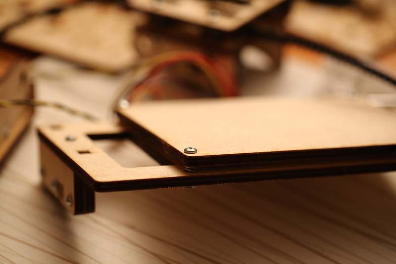
Result after a first round of cable management, actually might fit!

Update: Part 1 is available here and Part 2 here.

Printrbot jr assembly part 2

Day two of the build I spent more time, still had a lot of fun but also experienced the first issues, that still haven’t been resolved…. I also did a first test render of a time-lapse movie of the whole build, lots of fun! May or may not be published and posted here. :-)

Early on day two I realized what I first looked like a tiny little wrench (but ignored for a while since I also thought it might be a weird new component for the printer) actually was a little wrench! Cute and quite helpful.

Tiny printrbot LC wrench!

Tiny printrbot LC wrench!

Started before the kid went to sleep so I could pound the Z rods in. They were a bit tricky. I started out by sanding the holes at the top to even get them through, but on the bottom holes I used a rubber mallet with support under the bottom. Worked fine, but made a lot of noise.

Had to do a lot of sanding of the holes for the X/bed hinge rod as well. They were extremely tight. Would have been much easier to do before the base was mounted but taking it apart again after forcing the Z rods in was not an option. I took the screws off the X stepper to move it a few millimeters away so it would be a little bit easier to avoid damaging it. As a general rule from this point on I made sure to sand all of the holes for rods before assembling them.

Z rods and X/bed hinge finally in place!

Z rods and X/bed hinge finally in place!

X rods installed.

X rods installed.

It was a little tricky to tighten the X belt, felt like I got it pretty tight but after having carefully zip tied it I’m not sure if it’s good enough.

One of the zip ties on the X axis belt.

One of the zip ties on the X axis belt.

Next up was the Z coupler for the Z screw. I had already noted that the groove in one of the parts looked a bit weird, but didn’t realize how bad it would be. I first had an insane amount of wobble, it was really crooked. For now I’ve used some pieces of zip tie plastics to shim it but there’s still plenty of Z wobble. Have been googling and found some interesting options on ebay (aluminium couplers) but there’s also printable options. Let’s just hope I can get the wobble down to the bare minimum needed to get prints done.

The bad Z coupler.

The bad Z coupler.

The Y/Z sandwich was next. Lots of fun, had to sand a little bit to get the linear bearings to fit in the middle piece. Otherwise pretty easy to assemble actually.

The nut trap for the Z axis is mounted using very long screws, lots of fun if you're using a regular screwdriver!

The nut trap for the Z axis is mounted using very long screws, lots of fun if you’re using a regular screwdriver!

Y/Z sandwich done!

Time to get the ends of the Y axis together, nice feeling to see the pile of LC parts quickly shrinking to nothing. Less fun was the missing screws. I’m out of longer screws now, only a 1.75 inch left and that’s way too long. Needed one more 0.75 and one of the elusive 1 inch screws. So the back end of the Z axis is currently held together with one single screw. It feels surprisingly solid though. But I’m going to get an ISO M screw with some nuts to least have one that I can adjust the end stop with. It’s next to impossible to buy non-metric screws here, I’ve tried before to get screws for a server rack mount and they guy we sent to the local shops was laughed at for even asking…

The Y end that’s missing two screws…

The front Y end, aka the extruder mount.

Tightening the Y belt felt a bit easier than the X belt, perhaps because I had a tiny bit of experience. :-) I hope it’s tight enough, if it isn’t I’ll look at printed belt tightening options sooner rather than later!

One of the zip ties holding the Y belt.

One of the zip ties holding the Y belt.

Y assembly done! Belt pretty tight, will be interesting to see if it's tight enough.

Y assembly done! Belt pretty tight, will be interesting to see if it’s tight enough.

It was pretty to easy to get the big sandwich onto the Z rods, also adjusted the Z endstop, will add another nut for it to get less wobble. Saw that Brook had two in his video, only one in the instructions though. This looks nice as well.

Very happy with the progress during day 2!

Progress after day 2.

Progress after day 2.

So what’s left to do now is assembling the extruder/hot end, mounting it on the printer, make the cabling a bit more sane and finally get the printrboard in there. The latter looks a bit tricky actually, there’s a lot of cables and very little room. Would have been nice with some spare connectors and simply cut the cables where appropriate to get custom lengths instead.

Update: Part 1 is available here and Part 3 here.

Printrbot jr assembly part 1

Finally got some time to work on assembling the actual printer. Started out with going through the LC parts to check if they were all there. Also snapped some photos of other components:

All LC parts

printrbot

printrbot_screws_and_nuts

Screws, nuts, etc. Nicely packed in sealed plastic bag.

printrbot_rods_and_lc_parts

Rods, note the two shorter ones are taped and tagged that they’re for the X carriage.

Two big and two small stepper motors. There’s a sticker on the printed copy of the BOM about the uses of the two different sizes, see below.

printrbot_stepper_motors

The stepper motors with the power supply in the background.

The herringbone gears seem to mesh pretty well even though they don’t look very pretty in some places, but I’m probably replacing them with normal gears eventually, when the printer is up and running that is. Or perhaps do what I’ve seen others do and order them from Shapeways instead.

printrbot_hotend_parts

Herringbone gears and the rest of the extruder kit.

Saw someone else the other day that also had JR written on a couple of places on the printrboard. My guess is that they printrbot guys have configured it with the proper dimensions? Can’t find the printrbottalk.com thread right now.

printrboard_1

printrboard from above

printrbot_2

printrboard from the side

Note that the printed copies of the BOM and the laser cut part numbers are newer than the ones on the web site!

printrbot_lc_parts_overview

printr bot lc part numbers

printrbot_jr_bom

printrbot jr updated BOM

It’s a bit difficult and slightly scary at first to snap off the remaining small tabs of plywood that connects the laser cut pieces. So far I’ve only managed to damage one of the pieces that’s not used, a couple of layers of plywood broke off. Would probably have been easy to fix with some wood glue though. After breaking them apart I use some small files to sand down the protrusions. Only one piece so far had some damage already:

Slightly damaged LC part, not a problem though.

Slightly damaged LC part, not a problem though.

The instructions are actually pretty good, make sure to use the new updated ones though, but it looks like they’re now the default. Videos are good, I’ve watched them a while back as I said in an earlier post but now I’m rewatching them at night in bed, and then I use the instructions when I actually do the assembly.

Started off with the base, as instructed. There is a lot of creaking and some force needed, but as Brook says in the video that just feels good. Had to leave the screws very loose to retain some flexibility for when the first part of the lid went in, it was a bit tricky.

Pieces for the base.

Pieces for the base.

Base done!

Base done!

Z endstop in place!

Z endstop in place!

Z stepper in place.

Z stepper in place.

Locking mechanism for the foldable bed.

Locking mechanism for the foldable bed, test mount to check if it fits.

X carriage with endstop.

X carriage with endstop.

It’s a little tricky to get this sandwich screwed together, but there’s a good tip in the instructions.

X carriage again, with stepper, pulley, bearings and belt.

X carriage again, with stepper, pulley, bearings and belt added.

A weird thing with the instructions for the ends of the print platform is the screw lengths, the single screw that’s supposed to have a nylock on it is too long, I don’t have any 1″ screws at all. Only 0.5, 0.75, 1.25 and 1.75 if I remember correctly (used my digital caliper since I suck at imperial measurements). We’ll see how things work out later on, worst case I’ll be missing screws of the appropriate lengths later and I guess I might have to saw of a bit of the one sticking out of the nylock nut now. I’m guessing it’s there to press on the X endstop switch? Need to check if there’s any M screws and nuts that is a good fit instead of the 6-32 (!) screws and nuts.

printrbot bed mount with leveling springs.

printrbot bed mount with leveling springs.

Progress so far.

Progress so far.

Update: Part 2 is available here and Part 3 here.

Printrbot Power Tower assembly

After assembling the birch spool I upped the difficulty level slightly and decided to take on the Power Tower. Still easy compared to the actual printer, but allows you to start getting a feel for how much you should tighten the screws.

Power Tower bag

All of the Power Tower laser cut parts, screws, nuts, bearings etc came in a sealed plastic bag. Note the fan cutout in one of the sides, it doesn’t seem to be there in the instructions, but very nice if you change to a more powerful power supply that either has a the fan on the bottom or has two fans. After opening the bag I put everything in a nice little pile.

printrbot_power_tower_parts_2

Power Tower parts

And then I sorted the screws, and figured out which had which length (I love the metric system).

printrbot_power_tower_screws

Power Tower screws and nuts

As you can see on the picture above there’s a bunch of pieces of wood that the laser hasn’t fully succeeded in cutting all the way through. With the help of a sharp knife and some force I got them out, you can see them below:

printrbot_power_tower_leftovers

Power Tower LC leftovers

After that it was pretty easy to follow the guide and assemble the tower. The only real problem I had was that the rear cutout that fits onto the back of the power supply didn’t quite fit. I used a file to make some more room for the power socket plastic frame, followed by a bit of force. Paused to take a picture when I was about halfway done, before the spacers and bearings on the top half for the spool:

printrbot_power_tower_halfway

Power Tower halfway

As you can see above I also got some zip ties and tried to make the cabling look a little bit nicer. Getting rid of the unused connectors would be nice… Didn’t take long to finish up, a good tip is to make sure the screws near the top aren’t tightened, otherwise it’s next to impossible to get the spacer plywood pieces in there.

printrbot_power_tower_done

Power Tower done!

Printrbot jr kit has arrived

A while ago I got really intrigued by FDM 3D printers. The reasonably priced ones are  quite crude still, showing their reprap roots. Very few if any options exists if you just want to plug & print and they’re still pretty expensive considering what you get. After finding the kickstarter project for the Printrbot jr I started to think it might be a good compromise. It’s fairly cheap but still pretty capable and easy to hack/modify.

When the kickstarter project that I backed on impulse failed I continued reading a lot, viewed the assembly videos, read Make Magazine’s guide and agonized a bit. Then I finally ordered the Jr kit with some extra accessories on January 2nd. It was shipped on the 25th and finally got to Sweden with me picking it up the same day on February 4th. In addition to the Jr kit I also purchased the Printrbot Power Tower, a birch filament spool and an additional 1kg spool of natural PLA filament.

Unboxed printrbot contents

Unboxed printrbot contents

As you can see in the picture I got the Jr version with an ATX power supply, either because they’re only shipping the newer version with a small 12V adapter in the US or because I ordered the Power Tower. I might want to add a heated bed later on for ABS plastics so I’m happy with the ATX power supply though. Very nice that the 1kg of PLA filament came on a printrbot birch spool.

After a rough check that all of the parts seemed to be there I decided to start with the birch spool and then put the 1lb roll of filament that was included in the kit on it. Putting together the spool sort of eases you into the business of laser cut plywood mounted together with weird (to me) imperial screws and nuts. Getting the filament onto the spool wasn’t as easy as you would think, got the tip later on from a friend that heating it up a little bit would have helped (only to 30 degrees C). It did not act very friendly at all at noral room temperature.. The one to the right below is the one I put together.

Printrbot birch spools

Printrbot birch spools

I plan to keep adding posts detailing my progress! Next up is the power tower!